 Español
Structural Static Analysis of Steel Silo
The spiral steel silo was invented by German Lipp in 1968, which has been booming in recent years in China. Technologies of steel silo are respectively complex in four aspects of structural behavior, failure mechanism, analytical method and manufacture & installment. At present, the research on the silo, especially in China, is still rather insufficient, and as the steel silo is more and more applied in the industrial and agricultural production, many problems in use are needed to be solved.Manufacture and Structural Features of Steel Silo
The spiral steel silo shall be constructed in top-down order, that is to say, first complete construction of silo roof and then finish each part subsequently from top to down to the silo bottom at last. Silo roof is the prefabricated part that consists of several fan-shaped steel plates, which its span is the same as diameter of silo body. Fan-shaped steel plates are fixed on the body through tightening connecting edges, supported by a closed arch on the top ridge of the roof with the stiffener. Cylinder body is manufactured by special machine through processes of spiral bending and undercut to form spiral embossed strip with 400mm wide outside the body which can improve silo strength and resistance to torsion. Undercut process is to be automatically machined at some certain speed, forming as the bearing support’s spiral upward. When the silo reels to 1m high, silo roof is finished; when the silo reaches designed height, after withdrawing coil opening machine and forming machine, undercut machine begins to reverse positioning and make silo landing, and then weld steel plate to the stiffener. In order to better undercut of connecting edges without warping, tensile stiffeners shall be welded on the inner wall of silo and pre-embedded part on base plate at bottom firmly. Finally, put them with the edge of the lower part of the cylinder together on iron anchor on the base by concrete pouring to enhance the overall stability of the silo.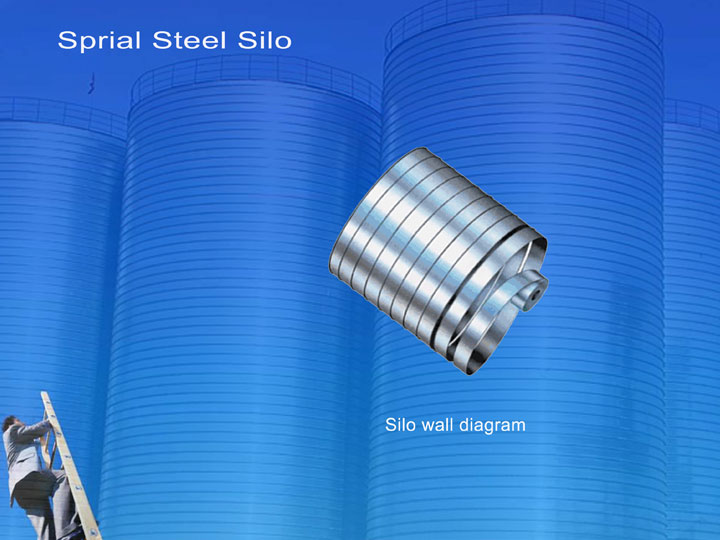
Steel Silo's Loading Function
In order to make it easy to calculate the following basic assumption: (1) The storage material is in a static state; (2) The vertical pressure of S at any depth is Pv , evenly distributed; (3) The horizontal pressure at any point of storage material is Pho , Pho is in the direct ratio to Pv , that is, Pho = K·Pv (K stands for active lateral pressure coefficient of storage material ); (4) The frictional resistance of storage material’s sliding along silo wall: Τ=μ·Pho +η(ηstands for cohesion of storage material, it is very small compared to its gravity ); (5) It is assumed that silo is infinite in depth,neglect effect of silo bottom to storage material pressure. (6) Density of storage material is uniform, incompressible granular body.Unit Classification of Steel Silo
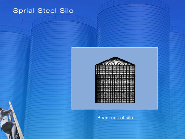
The spiral steel silo is composed of vertical struts and steel plates, which is connected by undercut between plates. In the structural internal force analysis, undercuts shall be seen as stiffeners, the plates as plate wall supported on vertical struts and stiffeners. According to the characteristics of this model, silo can be divided into two types: plate unit and elastic beam unit. Plate unit is the four-node curved surface unit which can reflect the reality of wall geometric shape and continuous condition of deformation; elastic beam unit is the two-node unit which can analyze vertical struts and stiffeners.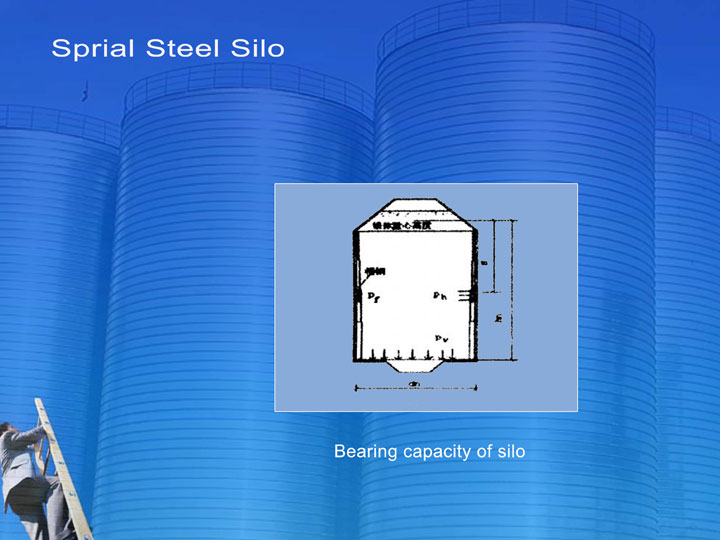
Spiral Steel Silo's Practical Case
Here just take some steel silo as the practical case. Supposing that silo is 20m in diameter, 22m in wall height, 4.5m in roof height and 2m in diameter of feeding inlet. From 0m to 16m it is equipped with 66 rows of [16b, [14b and [10 channel steel; from 16m to top it is equipped with 33 rows of [8 channel steel. On the cone surface of the top it is equipped with 66 pieces of [6.3 channel steel; 16mm×200mm ring beam is installed at tops of feeding inlet and cylinder silo. The section of stiffener is 20mm×30mm when two pieces of 4mm steel plate under cut, 30mm×16mm when 3mm, 30mm×10mm when 2mm. Undercut height is 376mm. The elasticity and shearing modulus of the steel plate are 206kn/m2 and 79kn/m2; compressive, tensile and shearing strength of the steel plate are 215n/mm2, 215n/mm2 and 125n/mm2; Poisson ratio and density of the steel plate are 0.25 and 7850kg/m3; grain gravity and inner friction angle are 7.5kn / m3 and 250; friction coefficient of grain and silo wall is 0.3.Unit Classification
The wall unit of spiral steel silo is the four-node curved surface unit, which the plate distance in the vertical direction shall be identified as 0.4m (the actual undercut distance of 0.376m) and the plate width is equivalent to distance between two adjacent struts. Silo roof along the radial direction is divided into 15 equal parts. Along the circular direction it is divided into 66 equal parts. The strut along the height direction is divided into 0.4m high short beam which takes the two-node as a unit. The undercut of plate, i.e. the stiffener, shall be also seen as the ring beam of which length is calculated on the distance between two adjacent struts. The ring beams of silo feeding inlet and the top of silo wall are 16mm x 200mm equally. Unit division is based on the strut intersection point. According to statistics, the number of the model units and node number are respectively 12045 units and 4686 nodes.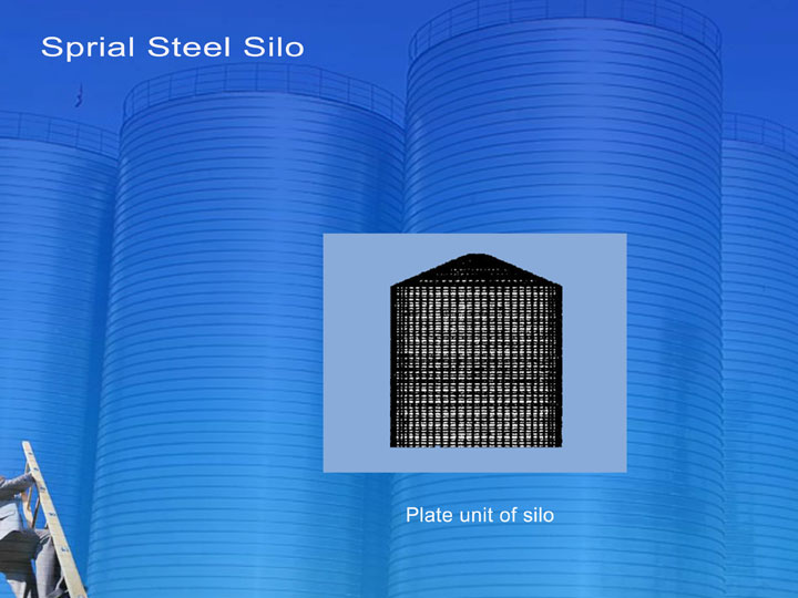
Loading Calculation
Combined with the characteristics of model, according to wind loading calculation formula: wk=βzμsμzW0 (kn/m2),we take variable values are as follows: μz belongs to B class standing for rough ground; βz=1.0;μs=1.3; W0=0.7; the silo is divided into nine regions along the height direction.
| Part Number |
Part Height Range (m) |
Height(m) | Wind Pressure |
| 1 | 0.0-3.2 | 1.60 | 0.833 |
| 2 | 3.2-6.0 | 4.60 | 0.927 |
| 3 | 6.0-8.0 | 7.00 | 0.990 |
| 4 | 8.0-10.8 | 9.40 | 1.045 |
| 5 | 10.8-13.6 | 12.20 | 1.102 |
| 6 | 13.6-16.0 | 14.80 | 1.150 |
| 7 | 16.0-19.2 | 17.60 | 1.198 |
| 8 | 19.2-22.0 | 20.60 | 1.245 |
| 9 | 22.0-26.5 | 24.25 | 1.297 |
Storage Loading
The concentrated loading of feeding inlet of the model shall be calculated on 7.35kn/m. Because of the unit loading way of beam, its concentrated loading is equivalent to the node loading of the top ring beam which is equivalent to 700n each. The cone surface loading of silo roof of the model shall be calculated on 0.3kn/m2. According to the actual loading area of the cone surface of each node, the loading is equivalent to the node loading. In addition, silo gravity is calculated on 76.93kn/m3.Loading of Working Conditions
Finite element analysis is calculated through using Msc. Marc software 2001. static linear elastic analysis of working conditions include as following: (1) the first analysis only on the action of wind loading; (2) the second analysis only on the action of level pressure of storage material; (3) the third analysis on the joint actions of both level pressure of storage material and friction; (4) the fourth analysis on the joint actions of wind loading, level pressure of storage material and friction. In addition, the structural weight, top surface loading and the concentrated loading of silo roof is always involved in combination.The Results of Finite Element Analysis
The first analysis shall face the most unfavorable situation if silo is empty. Because wind loading always forms a symmetric impact, stress and deformation only on its action shall also be symmetric. Therefore, the analysis of stress and deformation for silo is only made along the wall height direction. Maximum horizontal displacement and main principal stress should be 3.9mm, i.e. change of horizontal displacement is 1.955 X 10⁻¹ andσmax9.609 X 106n/m2. The allowable displacement and stress of silo are 1.0 ×10⁻³ and 2.15×10⁸n/m2 respectively. So the stress and deformation of the silo only on the action of wind loading can meet allowable conditions, the structure is stable.
The second, third and fourth analysis respectively stands for the possible state of full silo. Comparatively speaking, the fourth analysis is the most unfavorable state. Considered permissible value, its relative maximum horizontal displacement and the maximum main stress are slightly more than the maximum permissible value of stress in 2.0-3.0m high (relative height is 0. 1-0.15).
By finite element analysis on the structural static of spiral steel silo using Msc. Marc software, in the range of the relative height from 0.1m to 0.15m at lower part of silo wall the stress and deformation is bigger due to friction and horizontal stress is big. Under the conditions of the model, the stress and deformation have been slightly more than the allowance.